
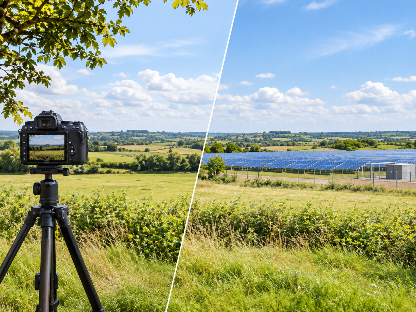
Photorealistic Integration Studies for Renewable Energy Projects: What Makes a Depiction Defensible
Most large solar, wind and storage projects are decided partly on how they will look during installation and operation. Planning authorities, neighboring communities and heritage bodies form a view of visual impact long before anything is built, and the material they form it from is a set of images produced by the applicant. That places an unusual burden on those images: they are marketing in origin and evidence in use.
The problem is that a photorealistic study is easy to make persuasive and hard to make verifiable. A slightly wider lens, a viewpoint moved fifty meters downslope, mature planting drawn where a hedgerow currently stands two meters tall — none of these are obviously dishonest, and all of them change the conclusion. When an objector or a reviewing landscape architect repeats the exercise and gets a different answer, the applicant loses more credibility than the original image ever gained.
A defensible integration study is therefore defined less by rendering quality than by whether someone else could stand where the camera stood, hold the print at the stated distance, and see what the image says they will see.
This article sets out how a verifiable photomontage is built for a renewable energy scheme — viewpoint selection, photography, the 3D scene, the render and the presentation — and where each stage commonly fails.
Choosing and agreeing viewpoints
Viewpoint selection decides the outcome more than any later step, which is exactly why it should not be the applicant’s unilateral choice. The standard sequence is to build a zone of theoretical visibility from a terrain model, identify the receptors that matter — settlements, roads, footpaths, designated landscapes, heritage assets — and then agree a viewpoint schedule with the consenting authority before photography begins.
A schedule of roughly six to fifteen viewpoints is typical for a utility-scale solar or storage scheme. It should deliberately include the unflattering ones: the nearest dwelling with open aspect, the elevated viewpoint that sees across screening, the approach where the development is seen in combination with an existing scheme. A study that contains only distant and well-screened viewpoints invites the reviewer to commission their own.
Terrain quality matters here. A zone of theoretical visibility built on a coarse global elevation model will miss local screening and invent visibility that does not exist; one built on a bare-earth surface derived from LiDAR or photogrammetry, with vegetation and buildings handled explicitly, is worth arguing from.
Photography that can be reproduced
Baseline photography for a verifiable montage is a survey task, not a photographic one. The requirements are consistent across the main guidance documents in use — the Landscape Institute’s Technical Guidance Note on visual representation and the Guidelines for Landscape and Visual Impact Assessment among them:
- A full-frame camera on a leveled tripod at a stated eye height, commonly 1.5–1.65 m.
- A fixed focal length equivalent to about 50 mm on full frame, which approximates the scale at which the human eye judges distance. Wide-angle lenses flatten and shrink the development, and are the single most common source of a misleading montage.
- Camera position recorded by GNSS to a few centimeters where the viewpoint may be revisited, with bearing, date, time and weather logged.
- Overlapping frames stitched to a planar or cylindrical panorama where the scheme is wider than one frame.
- Season chosen honestly. Photography taken in full leaf, presented as year-round, is indefensible where deciduous screening does the work.
Building a scene that matches the site
The 3D scene has to be geometrically correct, not merely plausible. For a solar scheme that means the actual module and tracker geometry — single-axis trackers commonly reach 2.5–4.5 m at maximum tilt, and the row spacing follows the design pitch rather than a convenient value — together with inverter stations, transformer compounds, battery containers, fencing, access tracks and any cut and fill. The auxiliary structures are often the visually dominant elements at close range, and are the ones most often omitted.
The scene sits on a terrain surface from the project survey, and the camera is matched to the photograph using surveyed features visible in the frame. Reality capture of the site and its surroundings makes this step verifiable rather than iterative: reality modeling provides the georeferenced terrain, existing structures and vegetation volumes that the camera match is solved against, so the fit can be demonstrated with residuals rather than asserted by eye.
Vegetation deserves particular care. Existing screening should be modeled at its surveyed height, and proposed planting should be shown at a realistic establishment stage — a year-one and a year-ten view, clearly labeled, rather than a single image of mature planting that will not exist for a decade.
Rendering and presenting honestly
Lighting is matched to the photograph’s date, time and conditions rather than chosen for effect. Materials are given the reflectance of the specified product; modern modules with anti-reflective coating are dark and low-gloss, and depicting them as mirror-like or as matte black are equal distortions. Where glint and glare are a genuine concern — an airfield, a control tower, an elevated road — that is a separate quantitative analysis of solar geometry and receptor position, not something a render answers.
Presentation is part of the evidence. Verifiable montages are normally issued at a stated print size and viewing distance — around 820 mm wide viewed at roughly 500 mm is a common convention — and each image carries a metadata panel: coordinates, eye height, bearing, focal length, date and time of the baseline photograph, projection, and the distance to the nearest development element. Without that panel the image cannot be checked, and an image that cannot be checked carries little weight.
Where movement genuinely aids comprehension — a drive-through of an approach road, a seasonal or diurnal sequence — animations, simulations and video creation should follow the same discipline: real camera paths, real terrain, stated parameters. Animation that is not built on the same verified scene is illustration, and should be labeled as such.
Featured Projects
ARGO-E has produced multiple photorealistic integration studies for utility-scale renewable schemes in Greece.
|
|
|
|
|


Contact ARGO-E to scope a verifiable photomontage and viewpoint schedule for a renewable energy application.